Hardware
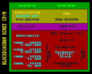
The following picture shows the main components of a KCNet interface. It is not a pure hardware solution, but a combination from hard- and software.

So far, implementations exist for our KC85 system and a card for K1520 bus systems, the standard bus of CP/M business computers in the former G.D.R.
A complete interface card for a Z80 system consists of a Z80-PIO with address bus decoder, data bus driver, control bus logic and the hardware of the KCNet-Interface.
Z80-System:
The M052- and K1520-implementations contain examples for Z80 bus connections. The "Zilog-Peripherals" board of "The N8VEM Home Brew Computer Project" is also a good starting point for the Z80 side of the hardware:
You can use a possibly existing PIO of your system too, then only the interface-hardware is necessary.
The whole network-software runs with a polling device-driver at this time. It could be beneficial later, if the PIO could operate via interrupt in the Z80 system.
KCNet-Interface:
The interface hardware needs a current of about 200 mA and is connected to the 5V power supply of the Z80-System. An additional voltage of 3,3V is required for the network-module (the KCNet and K1520 circuits contain examples).
Circuit diagrams are available from the following implementations:
| KCNet experimental board | - | development board of the KCNet project |
| Network & USB Module M052 | - | special solution for the kc85 hardware-module bus |
| K1520 experimental board | - | basis for a common K1520 bus card |
The circuit components are:
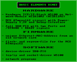
- WIZnet Plug-in network module with the hardware TCP/IP stack (W5100 or W3150A+)
- 3,3V power regulator
- MCU ATmega 162 with reset generator, quartz generator 8 MHz and an individualized copy of the Firmware (unique MAC address !)
- 74HCT573 address latch
- 74HCT00 or 74HCT04 with inverting buffers
- 74HCT08 with 2-input AND gates (only necessary with network module WIZ810MJ)
- driver/receiver MAX232 for a standard RS-232 communication interface of the Debug-Terminal
- ISP plug for firmware programming (optional)
All components are commercially available and easy to get at electronics retailers.
The network modules are available at selected dealers or distributors of WIZnet. They can be ordered in Germany at www.dacomwest.de or www.watterott.com, for example.
Network Modules:
There are different WIZnet modules. You need one with 8-bit MCU bus interface and the "modified TCP/IP stack-II", in order to use the KCNet circuit and the Z80 driver software. There are some minor differences between usable modules. The network module WIZ811MJ is not suitable!
| TCP/IP stack: | W3150A+ |
| Connector Type: | two 2 mm x 14 Connectors |
| Dimension: | 52 mm x 25 mm |
| Notes: | connect /L_LINK output JP2:12 direct with MCU Pin 15 |
| TCP/IP stack: | W5100 |
| Connector Type: | two 2 mm x 14 Connectors |
| Dimension: | 52 mm x 25 mm |
| Notes: | connect /LINK_LED JP2:12 / TX_LED JP2:8 / RX_LED JP2:10 like in KCNet circuit with MCU Pin 15 and SPI_EN JP2:9 to Ground |
| TCP/IP stack: | W5100 |
| Connector Type: | two 2,54 mm x 10 Connectors |
| Dimension: | 55,5 mm x 25 mm |
| Notes: | connect /LINKLED J2:19 direct with MCU Pin 15 and pay attention to the following cross reference list (n.c. means not connected) |
Cross-Reference List WIZ810MJ - WIZ812MJ:
| WIZ810MJ | WIZ812MJ | ||||
| Name | Pin | Name | Pin | Note | |
| - | - | MOSI | J1:1 | n.c. | |
| - | - | MISO | J1:2 | n.c. | |
| D1 | J2:15 | D1 | J1:3 | ||
| D0 | J2:16 | D0 | J1:4 | ||
| D3 | J2:17 | D3 | J1:5 | ||
| D2 | J2:18 | D2 | J1:6 | ||
| D5 | J2:19 | D5 | J1:7 | ||
| D4 | J2:20 | D4 | J1:8 | ||
| D7 | J2:21 | D7 | J1:9 | ||
| D6 | J2:22 | D6 | J1:10 | ||
| GND | J1:8,13,24 | GND | J1:11 | ||
| VCC (3,3V) | J1:1 | VCC (3,3V) | J1:12 | ||
| A8 | J1:15 | A8 | J1:13 | ||
| A9 | J1:14 | A9 | J1:14 | ||
| A10 | J1:11 | A10 | J1:15 | ||
| A11 | J1:12 | A11 | J1:16 | ||
| A12 | J1:9 | A12 | J1:17 | ||
| A13 | J1:10 | A13 | J1:18 | ||
| A14 | J1:7 | A14 | J1:19 | ||
| - | - | n.c. | J1:20 | n.c. | |
| VCC (3,3V) | J2:24 | VCC (3,3V) | J2:1 | ||
| /RESET | J2:2 | /RESET | J2:2 | ||
| - | - | SCLK | J2:3 | n.c. | |
| - | - | /SCS | J2:4 | n.c. | |
| /WR | J1:3 | /WR | J2:5 | ||
| /RD | J1:4 | /RD | J2:6 | ||
| /CS | J1:5 | /CS | J2:7 | ||
| /INT | J1:2 | /INT | J2:8 | ||
| - | - | LED_RX | J2:9 | n.c. | |
| - | - | LED_TX | J2:10 | n.c. | |
| A0 | J1:23 | A0 | J2:11 | ||
| A1 | J1:22 | A1 | J2:12 | ||
| A2 | J1:21 | A2 | J2:13 | ||
| A3 | J1:20 | A3 | J2:14 | ||
| A4 | J1:19 | A4 | J2:15 | ||
| A5 | J1:18 | A5 | J2:16 | ||
| A6 | J1:17 | A6 | J2:17 | ||
| A7 | J1:16 | A7 | J2:18 | ||
| - | - | /LINKLED | J2:19 | direct to ATmega162 Pin 15 | |
| GND | J2:1,4,7,13,14,23 | GND | J2:20 | ||
Reproduction:
The block diagram shows the model for a common CP/M 2.x system. All network programs should work on every system, because of the standard system CALL's. For now, the complete driver software for a KCNet interface is integrated in the application, not in the BIOS. The PIO I/O address of the system and exotic Terminal Codes can be adjusted in one config file for all programs before the translation.

The building of an interface card for other systems shouldn't be a problem for advanced users. We can share our knowledge and assist you with our implementation experiences, but making one is your task. The implementation and test of such a card has to be done with the hardware of your systems : we can't do it for you!
Reproduction is relatively simple, because of the comparatively very low hardware cost. The use of a Z80 standard circuit and the built-in Debug-Terminal make it considerable safe. A problem should be found fast and easy in case of troubleshooting. A terminal program let you "look into" the MCU system via the debug-interface. This tool allows a test of the hardware TCP/IP stack independent from the Z80 system and monitoring the communication between MCU system and Z80 system in realtime.
The connection to an existing Ethernet home network is done with a simple network cable. All properties, including Ethernet crossover cable, are recognized automatically. The chip supports the PPPoE protocol via DSL modem too. This protocol is not supplied by the current software, but it could be programmed in principle.
There are some restrictions with the W5100. Only IPv4 is available, it can do 4 simultaneous connections to the network only, and it does not support IP fragmentation. But these restrictions have absolutely no significance in a private home network.
I was very happy in January 2008, when the KC had done its first connection to the PC in my network. The primary software applications are client programs. I don't have the intent to use my KC85 as an internet server :-) !

