- Details
- Geschrieben von Ralf Kästner
- Hauptkategorie: Network
- Veröffentlicht: 03. Juni 2009
- Zugriffe: 51182
Debug-Terminal
After describing the interface hardware, we finally come to an important tool for builders. It is especially needed in case everything was made seemingly right in the Z80 system, but nothing happens when trying to test the interface with the Z80 software.
On the other hand, if the interface communicates immediately with the Z80 system, you can skip this section.
The terminal interface to the debugger has a second important function. The KCNet configuration data for the adaptation to the host system can be viewed safely only in this way.
The debugger works like a terminal. You need a keyboard, a screen and a serial interface. When a button is pressed, the key code is sent through the serial interface to the controller, the firmware in the controller processes the code and an answer is sent back via the same interface, which is displayed on the screen.
With the debugger, you obtain access to the MCU system, even without a functioning communication to the Z80. In this way, the complete hardware behind the Z80-PIO can be checked easy, in order to diagnose errors. If the ATmega works, you can test the memory interface and the function of the W5100 also. The real-time display of the PIO communication was a very useful feature in the beginning of the development. You are able to monitor the input- and output-streams to ensure that the commands of the KCNet protocol are processed correctly.
RS-232 cable:
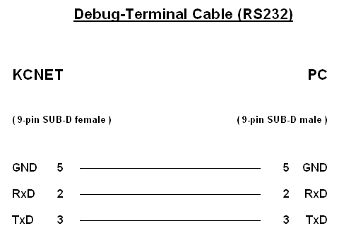
The common junction of the Tx- and Rx-lines is made behind the KCNet port, so that a commercially available 1:1 serial extension cable can be used, not a null modem cable! As you can see on the picture, the communication takes place without handshake, so that you don't have to deal with the remaining signals of the RS-232 interface.
That's all. After connecting, you can start the terminal software on the PC.
Terminal program:
The following description refers to the Windows program HyperTerminal. First, the communication parameters must be set correctly, after starting HyperTerminal:
interface:
- COM number
- Transmission speed 9600 Baud
- 8 Data bits
- 1 Stop bit
- no Parity
- no Handshake
ASCII-configuration:
- finish sent lines with line feed ON
- echo local character input ON
- attach line feed at received lines OFF
- receive input data in 7 Bit ASCII format OFF
- wrap too long lines in the terminal-window OFF
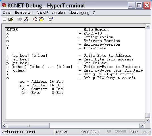
If not, check and verify once again the connection, the cable and the settings of the terminal program, etc. If you cannot find any errors there, either a mistake in the programming of the controller happened (check the fusebits and the contents of the EEPROM), or there is a problem with the hardware itself, which must be further investigated.
However, if the Help Screen appears in the terminal window, it looks quite good. This means that the controller system is running and no more critical errors have to be expected.
Debugger:
The debugger is installed in the firmware of the controller, and can be controlled from the terminal program with the help of defined commands.
Each executable command begins with the letter at the left edge, and must be completed with the ENTER key always. Use the ENTER key on the main keypad, not on the number pad!
If you send ENTER without a letter to the interface, the terminal window is cleared and the help screen rebuilt completely.
Be careful, when specifying parameters. The following rules apply:
- input 2 HEX characters for 8-bit values
- input 4 HEX characters for 16-bit values
- leading zeros must be declared
- exactly 1 space must be declared between command and parameter(s)
- no Case sensitivity
- each command must be completed with ENTER
The debugger replies on a violation of these rules with the error message "Syntax Error!" and you must start again from scratch.
Read the configuration data:
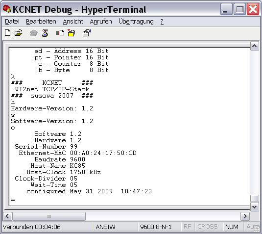
First, the configuration data should be verified. The controller reads these data from its memory directly. Therefore, this test must always work, if it was programmed correctly. The following picture shows the display of the commands "k", "h", "s", "c":
Test the Network connection:
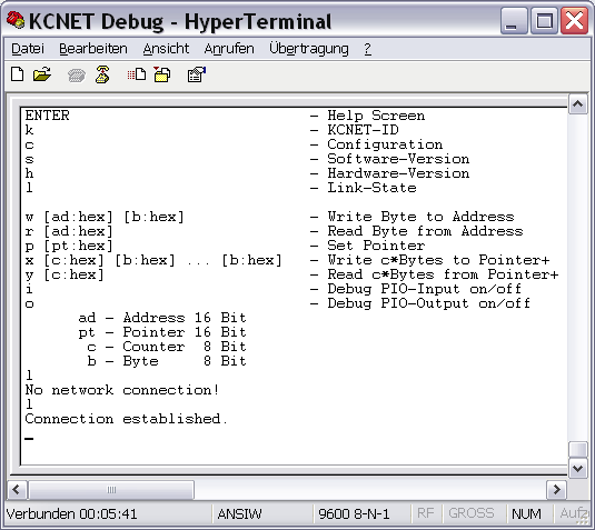
The W5100 reports on a port pin of the controller, whether there is a physical connection to the network or not. That would be the next test, which is carried out with the command "l".
The command "l" notifies with the message "No network connection!", if no network cable is connected with the network module.
If the interface is connected with the network switch or router, the green LED of the network module lights and the command "l" displays the message "Connection established.".
So, you know that the network module is working. If it does not, the error can be caused from the hardware up to the module only, or the network module itself, because the controller works.
Test the TCP/IP-Stack memory-interface:
The next step would be to review whether the RAM interface of the W5100 can be accessed without faults.
The commands "p", "x" and "y" are used for this purpose. The command "p" tells the debugger the address in the KCNet interface, where it has to read or write the bytes in the commands "x" or "y". After each byte, which has been transferred, the program in the controller increases that address independently by 1. So, you can read or write whole memory blocks of consecutive addresses at once.
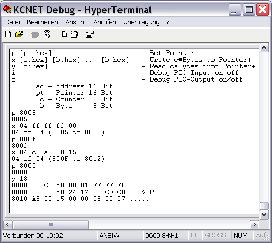
You should compare the relevant datasheet section of the W5100 with the commands and their parameters, to understand the test. Here, then, is the significance and impact of the commands, according to the following screenshot:
| p 8005 | - sets the address pointer to 8005H - there is the register SUBR (Subnet Mask Register) - the debugger quits the command with the written address in the following line |
| x 04 ff ff ff 00 | - writes 4 Bytes at once from the current address pointer with increasing address:
8005H=FF- now, the register SUBR contains the Subnetmask 255.255.255.0 - the debugger quits the command with the written addresses |
| p 800f | - sets the address pointer to 800FH - there is the register SIPR (Source IP Address Register) - the debugger quits the command with the written address |
| x 04 c0 a8 00 15 | - writes 4 Bytes at once from the current address pointer with increasing address:
800FH=C0- now the register SIPR contains the IP 192.168.0.21 - the debugger quits the command with the written addresses |
| p 8000 | - sets the address pointer to 8000H - the debugger quits the command with the written address |
| y 18 | - reades back 24 Bytes at once from the current address pointer with increasing address - the debugger sends a HEX/ASCII-dump to the terminal program - every line shows 8 Bytes with address, HEX-Bytes and ASCII-Bytes |
Now, this output is compared with the previously transmitted input at the addresses of the SUBR and SIPR registers. Only when the same content is displayed in the terminal dump was the test successful.
If not, the hardware connection from the controller to the network module is faulty. Then, all lines of the MCU bus interface, as well as the address and data bus, must be checked.
The W5100 works in the network already, if everything is correct. You can PING from other parties in the same network to the entered IP address, and the KCNet interface answers.
Test the TCP/IP-Stack function:
Since the chip is put into service through the writing of memory addresses, one can do a function test in this way. You write a command into a register of the stack, and observe whether it is performed correctly.
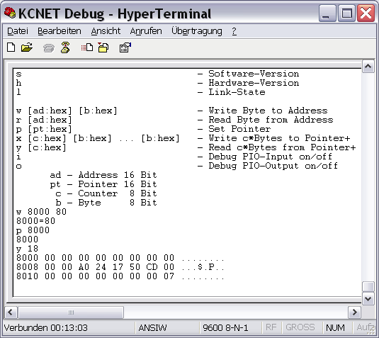
The following steps perform a software reset. Afterwards, all of the above entered parameters must be cleared:
| w 8000 80 | At address 8000H is the MR Register (Mode Register). Setting Bit 7 of this register triggers the software reset. - writes the Byte 80H (10000000B) to address 8000H - the debugger quits the command with the address and the written Byte |
| p 8000 | - sets the address pointer to 8000H - the debugger quits the command with the written address |
| y 18 | - reads back 24 Bytes at once from the current address pointer with increasing address - the debugger sends a HEX/ASCII-dump to the terminal program - every line shows 8 Bytes with address, HEX-Bytes and ASCII-Bytes |
The TCP/IP-stack is back in the state, such as after power on. All registers have been reset and are loaded with their default values. Even the Bit 7 of MR is then cleared automatically.
As you can see, the inputs are gone, all the registers were set to the default value 0. The PING to the previously given IP address is no longer answered.
Test the Z80-PIO communication:
Finally, we come to the last test. Now, the KCNet interface must be connected to the Z80-System, because we want to check the link between the Z80 bus and the MCU system. Start the interface test program CPMNET.COM at the Z80 system, and go to the interface menu. There are some functions which send appropriate test commands of the KCNet protocol to the MCU system.
Use the commands "i" and "o" of the debugger in order to activate the realtime display of data traffic to and from the Z80-PIO. Next, send test commands to the interface with the help of CPMNET.COM. All data sent from the Z80-PIO to the controller, and sent back from the controller to the Z80-PIO, will appear in the window of the terminal program simultaneously.
The following picture was taken, however, with the program CAOSNET.KCC on a KC85 system. The CP/M program sends additional sequences to the interface between calling menu commands, which hangs together with the menu management of CPMNET.COM. Therefore, the displayed data are the same under CP/M in principle, but don't agree fully with the screenshot.
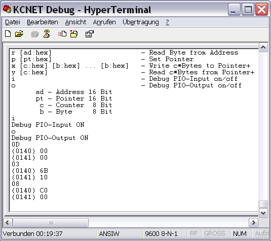
The screenshot shows the following commands of the KCNet protocol with their answers from the interface:
| Command | # DEC | # HEX | Answer | Value |
| Read Command Errors | 13 | 0D | 0000 | 0 Errors |
| Read Timer | 3 | 03 | 106B | 4203 ms |
| Read Dynamic Port Number | 8 | 08 | C000 | Port 49152 |
If nothing happens or there is something wrong, the failure lies in the hardware of the Z80-PIO, the Z80 bus logic, or in the interface connections from the Z80 system up to the controller.
All bracketed numbers are address information, which not belong to the protocol. These extra information is added from the debugger in realtime, so the answers are more understandable and more readable. If a question mark is displayed, the controller has not understood the PIO command. Such a sequence causes a command error in using the KCNet Protocol!
Please switch off the PIO protocol functions, if you don't need them! Both functions restrict the transmission speed to 9600 baud, this greatly slows down the PIO communication, too!
The sent addresses from the terminal program are not checked : you have full access to the entire RAM of the controller. One should, therefore, not write to the addresses from 0 to 500H because, otherwise, the firmware can crash!
Those, who arrive at this point successfully, have achieved the goal : the interface should work in the Z80 system!
As already explained, you can also execute the last test with the Z80 software immediately. If everything is running, then it's okay. But if nothing happens, you should do, step by step, the specified tests in order to isolate the cause of the malfunction.
Another important point right at the end : if the diagnostic interface is not used currently, there nothing should be connected! Once a character is sent from the outside to the controller, it stops everything else and is waiting for the end of the reception, which is the ENTER key code. If it does not come, the PIO interface is blocked!
For example, Linux systems send bytes to the COM port during the boot sequence and thus block the Z80-PIO communication. Looked from the perspective of the Z80 system, the interface behaves like defect!
- << Zurück
- Weiter
